When our team (Annie, Lara, and Hampton) was first given the wire assignment, we immediately thought of theoretically and materially engaging with metals throughout the design process. As we learned in the examples of Anish Kapoor’s Cloud Gate, Calder’s statues, as well as Amy Ogata’s talk on various metallic surfaces in Imperial France, metals have qualities that enable and disable creation. Indeed, our group had to be aware of the oxymoronic qualities of metal as a material category: such as how metal can be both liquid and solid, flexible and terse. With metal’s constantly changing states in mind, we began by sketching some initial ideas, including a three-story triangular prism and a cube with a square-based pyramid top that would include a circular opening at its apex to hold the dixie cup. Narrowing in on a rectangular prism, we decided that the structure we would set out to build would incorporate some of our primary sketches’ ideas. From this point, we agreed upon what we thought was our final design: a three-story rectangular prism reinforced with load-bearing beams set at alternating forty-five degree angles.
Having resolved to create the intricate cuboid, we began straightening out the three types of wire provided to us so that our ultimate wire cuts would be as precise as possible. First, we tried bending the wires in opposing directions from the various curves and slopes in their form. We soon realized, however, that the wire pieces’ material integrity could not be smoothed in this way, as the more we tried to straighten-via-bending, the more warped the wires became. Noting the propensity all three wires had for warping, we decided that the most key wires to straighten were our steel strands, as they would form the basis of our structure, with the brass and copper ones serving as both supportive and decorative beams that would be cut into smaller pieces than those of the steel. Thus, we started trying to smooth out the warping within the steel wires in a few different ways, and ultimately found a process that worked best in stripping the wire against a table’s level surface while simultaneously placing pressure on its other end with the plastic handle of a pair of pliers. Although the steel wires were not perfectly straightened, the improvement in their uniformity allowed us to proceed in cutting various equal segments as per our designed structural blueprint.
Our bridge inspiration stemmed primarily from the class discussion held weeks ago that highlighted the fact that the Brooklyn Bridge was the first major manifestation of steel usage for the completion of a bridge. In this way, we aimed to similarly try to take full advantage of the material properties of steel in our structure’s completion, in much the same way that the Brooklyn Bridge exploits the manifold structural and aesthetic characteristics of steel in its understanding of (and presence and purpose within) the New York environment. Such considerations play out additionally in the manner in which we echoed the Brooklyn Bridge’s stark, geometric architectural aesthetic through our distinctive use of angularity made possible by the specific wire materials afforded to us. 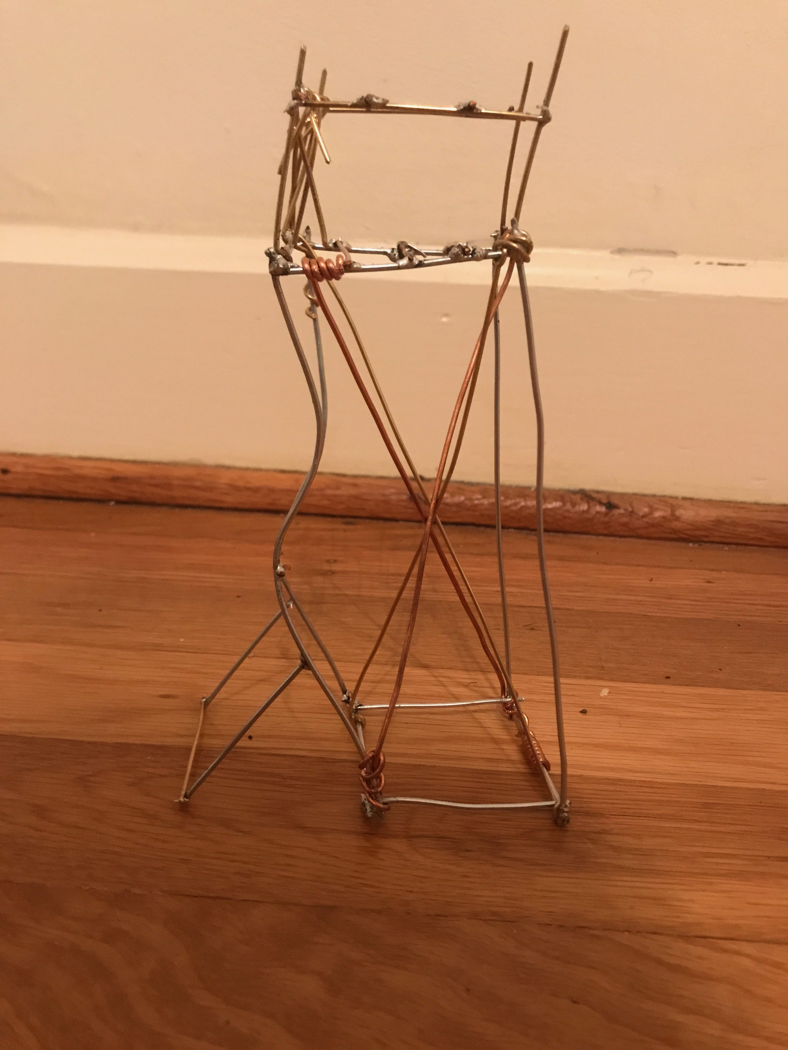
Since our group decided to focus on a design that was reminiscent of cable and cantilever bridges, such as the Brooklyn and Queensboro Bridges, we designed our structure with a focus on using wire pieces to support the form’s material integrity while also bolstering the linearity of its angular design. Thus, we had planned for our piece to be just tall enough to meet the assignment’s requirements—a total of six inches tall—so that we could use any extra wire to achieve our desired effect. Cutting our four main steel frame pieces and eight steel connecting pieces to be just over six- and two-inches long, respectively, we believed that we had given ourselves enough room for any potential errors that may come about with soldering. This assumption proved to be false, and upon finishing the soldered frame of the piece, we realized that we would have to alter what we had thought was our final design to accommodate the newfound lean in the structure. At this point, all of the steel wire had been cut into predetermined pieces and mostly used, while one of each of the brass and copper wires had likewise been cut. As a result of this tilt in our piece and the limited options that remained available to our team, we chose to bend the two tallest-standing six-inch steel pieces outward at their midsections to level the structure’s top. Although this helped the piece stand level, it also created a new issue for us: the structure was no longer six inches tall—in fact, it now stood at only five-and-a-half inches.
In order to compensate for this, out team decided to take the pieces that we had previously cut and add a platform to the top of the structure. We used the brass and copper wire segments for this, and found that, not only was it difficult to work with the two softer metals, it was also difficult to solder different metals together. It took several attempts to get each rod to attach to the side of the steel structure, and several of the rods broke off the top of the second platform multiple times before we could sufficiently solder them. When we added the top platform, which was identical in its grid-structure to the original top of the steel structure, the height now measured at six-and-a-half inches.
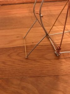
With this new addition, our team realized we needed to stabilize the structure further. Reengaging our original idea of triangular supports, we decided to add diagonal, load-bearing beams set at alternating forty-five degree angles. At this point, we had a full structure that had already been soldered, so, in order to avoid re-soldering over and over again, we decided to wrap the metal supports around the steel structure. This choice prevented us from re-soldering the corners of the main base. Additionally, the wrapping allowed us to straighten and truly enforce each of the beams. By stretching them to their breaking point, they truly acted as support for the added weight of the pennies. Our group thus utilized all of the nature of the metals provided–their ability to melt and harden, be straightened and pulled, curved and bent.